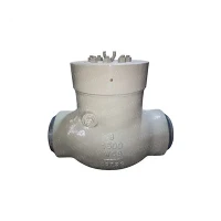
A swing check valve is a crucial component in many fluid handling systems. As a trusted swing check valves supplier, I am often asked about the flow pattern through these valves. Understanding the flow pattern is essential for optimizing system performance, ensuring proper valve selection, and maintaining the integrity of the entire piping network.
Basic Operation and Flow Principles
The fundamental design of a swing check valve consists of a disc that is hinged at the top and swings open or closed in response to the flow of fluid. When the fluid flows in the forward direction (the intended direction of flow), the pressure of the fluid pushes the disc open, allowing the fluid to pass through the valve. The disc is designed to pivot on its hinge, creating a relatively unobstructed path for the fluid.


As the fluid approaches the valve, it first encounters the closed disc. The force exerted by the fluid on the disc causes it to start swinging open. Once the disc is fully open, it is parallel to the flow direction, minimizing the flow resistance. This position allows for a smooth and efficient flow of the fluid through the valve. The flow pattern at this stage is similar to that in a straight pipe, with the fluid moving in a relatively laminar manner, especially in well - designed systems with proper piping layout.
Flow Characteristics During Forward Flow
In a well - functioning swing check valve during forward flow, the flow velocity distribution across the valve opening is relatively uniform. The fluid enters the valve with a certain velocity profile, and as it passes through the open disc, the profile is maintained or adjusted slightly depending on the valve geometry.
The area of the valve opening is a critical factor in determining the flow rate. A larger valve opening will generally allow for a higher flow rate, given the same pressure differential. The shape of the disc and the internal cavity of the valve also affect the flow pattern. A streamlined disc design helps to reduce turbulence and pressure drop. Turbulence can cause energy losses in the system, leading to increased pumping costs and potential damage to the valve and other components over time.
For example, in a water distribution system, a properly sized swing check valve will ensure that the water flows smoothly through the pipeline. The laminar flow pattern helps to maintain the pressure and flow rate required for efficient water delivery to consumers. If the valve is too small for the flow rate, the disc may not open fully, causing excessive turbulence and a significant pressure drop.
Reverse Flow Prevention and Flow Pattern Changes
One of the primary functions of a swing check valve is to prevent reverse flow. When the flow direction reverses or the pressure downstream exceeds the pressure upstream, the disc swings shut. The closing action of the disc is driven by the reverse pressure differential and the weight of the disc itself.
As the reverse flow begins to occur, the fluid exerts a force on the downstream side of the disc, pushing it towards the closed position. The flow pattern during the closing process is highly turbulent. The fluid that was previously flowing forward suddenly encounters an obstruction as the disc starts to close. This creates eddies and vortices in the fluid, which can cause noise and vibration in the system.
Once the disc is fully closed, the valve prevents any further reverse flow. The sealing mechanism of the valve ensures a tight closure, preventing leakage. However, in some cases, a small amount of leakage may occur due to wear and tear on the sealing surfaces or improper installation.
Impact of Valve Design on Flow Pattern
The design of the swing check valve has a significant impact on the flow pattern. Different types of swing check valves are available to suit various applications. For instance, High Pressure Swing Check Valve are designed to withstand high - pressure differentials. These valves often have a more robust disc and hinge design to ensure reliable operation under extreme conditions.
The material of the disc and the valve body also affects the flow pattern. A smooth - surfaced disc made of a low - friction material will allow for a more efficient flow. In contrast, a rough or corroded disc can cause additional turbulence and pressure drop.
The hinge mechanism is another important aspect of valve design. A well - lubricated and properly aligned hinge ensures that the disc opens and closes smoothly. If the hinge is stiff or misaligned, the disc may not open or close fully, leading to abnormal flow patterns and potential valve failure.
Flow Pattern in Different Applications
In the oil and gas industry, Oil Swing Check Valves play a crucial role in preventing reverse flow in pipelines. The flow of oil through these valves has unique characteristics due to the high viscosity of oil. The oil flow is more likely to be laminar compared to a low - viscosity fluid like water. However, the high viscosity also means that any turbulence or restrictions in the valve can cause a significant pressure drop.
In an oil refinery, swing check valves are used to control the flow of various oil products through different processing units. The proper flow pattern is essential for maintaining the quality of the refined products and the efficiency of the overall refining process. If the valve malfunctions and allows reverse flow, it can contaminate the product and disrupt the production process.
In industrial steam systems, swing check valves are used to prevent the backflow of steam. Steam has a high velocity and energy, and the flow pattern through the valve must be carefully controlled. A well - designed valve will ensure that the steam flows smoothly during forward flow and prevents reverse flow effectively. The high - temperature and high - pressure nature of steam requires the valve to be made of suitable materials that can withstand these conditions without significant degradation.
Flanged Swing Check Valves and Their Flow Considerations
Flanged Swing Check Valves are widely used due to their ease of installation and connection to piping systems. The flanged design provides a secure and leak - free connection. However, the flanges themselves can have an impact on the flow pattern.
The connection between the flange and the pipe may cause a slight change in the flow profile. If the flanges are not properly aligned or if there are irregularities in the flange surface, it can lead to turbulence at the valve inlet and outlet. This turbulence can then propagate into the rest of the pipeline, affecting the overall flow pattern in the system.
Importance of Understanding Flow Patterns for Valve Selection
As a swing check valves supplier, I emphasize the importance of understanding the flow pattern when selecting a valve for a specific application. The flow rate, pressure differential, fluid properties (such as viscosity, density, and temperature), and the nature of the system (e.g., whether it is a continuous or intermittent flow system) all need to be considered.
For a system with a high - flow rate and low - pressure differential, a larger valve with a streamlined disc design may be required to minimize pressure drop. On the other hand, in a system with a low - flow rate and high - pressure differential, a smaller valve with a more robust construction can be used.
Contact for Procurement and Technical Consultation
If you are in need of swing check valves for your application, it is essential to choose the right valve to ensure optimal performance. Understanding the flow pattern through swing check valves is just one aspect of making an informed decision. Our team of experts can provide you with detailed technical advice on valve selection, installation, and maintenance.
We have a wide range of swing check valves, including High Pressure Swing Check Valve, Oil Swing Check Valves, and Flanged Swing Check Valves to meet your specific requirements. Contact us to discuss your project and let us help you find the best solution for your fluid handling needs.
References
- Miller, D. S. (1990). Internal Flow Systems. BHRA Fluid Engineering.
- Idelchik, I. E. (2007). Handbook of Hydraulic Resistance. CRC Press.
- Crane Co. (1988). Flow of Fluids Through Valves, Fittings, and Pipe. Technical Paper No. 410.